|
IMPORTANT NOTE: THESE ARE INSTALLATION INSTRUCTIONS SPECIFIC TO A CABLE VERSION DIGI
(1996 Kawasaki without electronic Speedometer). PLEASE DO NOT ASSUME THAT THEY ARE RELEVANT TO ALL MOTORCYCLE INSTALLATION.
IF YOU REQUIRE FURTHER, MODEL SPECIFIC ADVICE, PLEASE CLICK HERE.
The installation below is easier with newer bikes that don't have a speedo cable as the sensor and magnets
are not needed. All the wires required are found in the loom behind the dials. Do not mount the sensor on the front
wheel of the bike, set-up is much more difficult if this option is chose!
Tools required
-
Soldering iron & solder
- Insulating tape
- Spanner of correct size
- Cross-head screwdriver
- Allen key set (One supplied with kit)
- Superglue
- Tie wraps
- Multimeter / Voltmeter / Probe
- Wire strippers
- Wire cutters
- Knife
- Paddock stand
Step 1
Be prepared to spend some time installing this, make sure you DO read the installation instruction BEFORE
you start!! Prepare the area you are working in. Use a blanket to stand the bike on (shows dropped part easier)
and use a cushion to kneal on; also put your tools within easy reach. Allow enough room to move around the bike and an area
to put the removed parts.
Start by mounting the supplied magnets into their plastic holders and then using the superglue supplied,
put the magnets into the allen bolt recess on the rear brake disc. (NOTE you may need to remove about a milimetre
from the depth of the holder and file off the exposed part of the plastic holder because as the wheel rotates the
holders can hit the brake caliper if the spacing is too tight), then using a suitable mounting bolt (the rear wheel
alignment bolt, or brake caliper bolt), secure the universal movement sensor bracket and adjust the gap between the sensor
and the magnets by tightening up the tiny grubscrew (apply superglue AFTER sensor is located correctly - after Digi is programmed),
which sets the position to approx 10mm. (5 - 15mm is allowed). Then route the cable from the wheel along the swing arm,
up under the seat and then forward to the clocks. It is advisable to wrap this loom with insulating tape, and tiewrap
in regular intervals to secure areas of the bike.
Step 2
To gain access to the wiring behind the clocks, remove the screen, then cut off the original cable ties
holding the wiring loom in place. This allows room to pull the loom up enough to gain access to the plugs and rear of
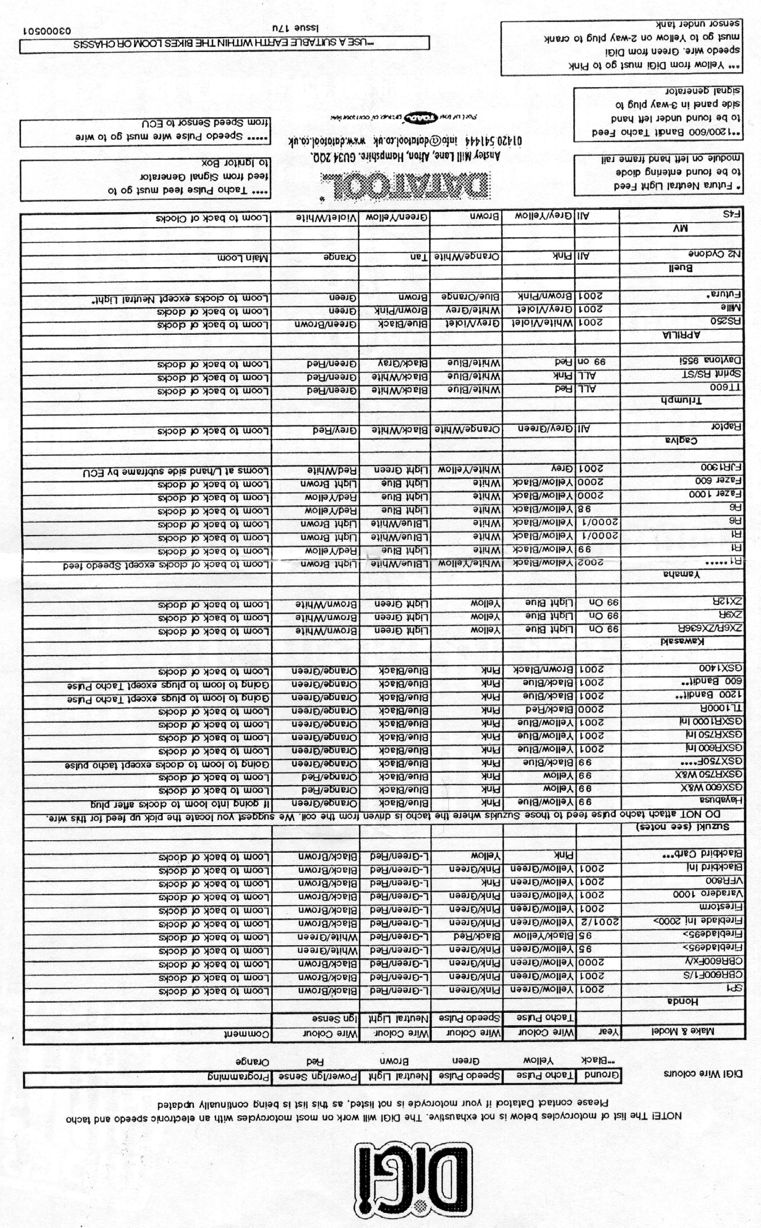
clocks. Then use a multimeter to find the correct wires needed, for this application they
were: Neutral - Light Green, Earth - Black/Yellow, Tacho pulse - Black with Yellow bands, Ignition
sensing - Brown/white.
Then carefully solder the Digi wires to these wires, making sure that the soldered wires are well insulated.
Digi Black - Earth, Digi Red - Switched 12v, Digi Brown - Neutral, Digi Yellow - Rev Counter, Digi Orange
- leave for programming.
Next the cables from the sensor need to be connected to the Digi wires:
Green - Digi Green, White - Digi Black, Brown - Digi Red - once these wires have been connected, insulate
and re-insulate the loom that you have opened.
Step 3
When all wires have been insulated, its time for setting up the Digi; switch on the ignition with the bike
in neutral and kill switch in the 'ON' position. When the display reads '0', touch the Orange wire to earth until the
display reads 'P', this can take up to 60 seconds, so persevere. Then touch the Orange wire to an earth once for every gear
your bike has (If it has six, touch the Orange wire to ground six times), each time the Digi increases by one count. Once
this is done, wait for the digi to return to '0'. DO NOT SWITCH IGNITION OFF, GO TO NEXT SEQUENCE.
Step 4
Make sure that your motorbike is on it's PADDOCK STAND. Start engine, an '0' is
displayed. Select first and let the clutch out, IT IS IMPORTANT TO HOLD THE THROTTLE AT A CONSTANT LEVEL - ABOUT 2,500RPM
WORKS WELL, once the '1' displayed increases in frequency and then shows a line across LCD - SLOWLY change into
neutral again and then into second. The Digi must see the '0' as the change is made. Again as the frequency increases of the
flashing '2' and then a line appears, change into 3rd and so on. Once all gears are done the Digi does a loop effect on the
dislpay and its all done. At this point, insulate the Orange programming wire, and tidy the loom area up.
Step 5
Next go for a ride, changing up and down the gearbox but be carefull until your happy all is OK. I found
that the digi takes about 2-3 seconds to know which gear you are in but changing down takes a while longer. Also, the
digi will not read whilst the clutch is in.
The picture below shows the mounting position chosen for the digital display, its
easy to read and the dark screen enables it to look brighter.

|
|